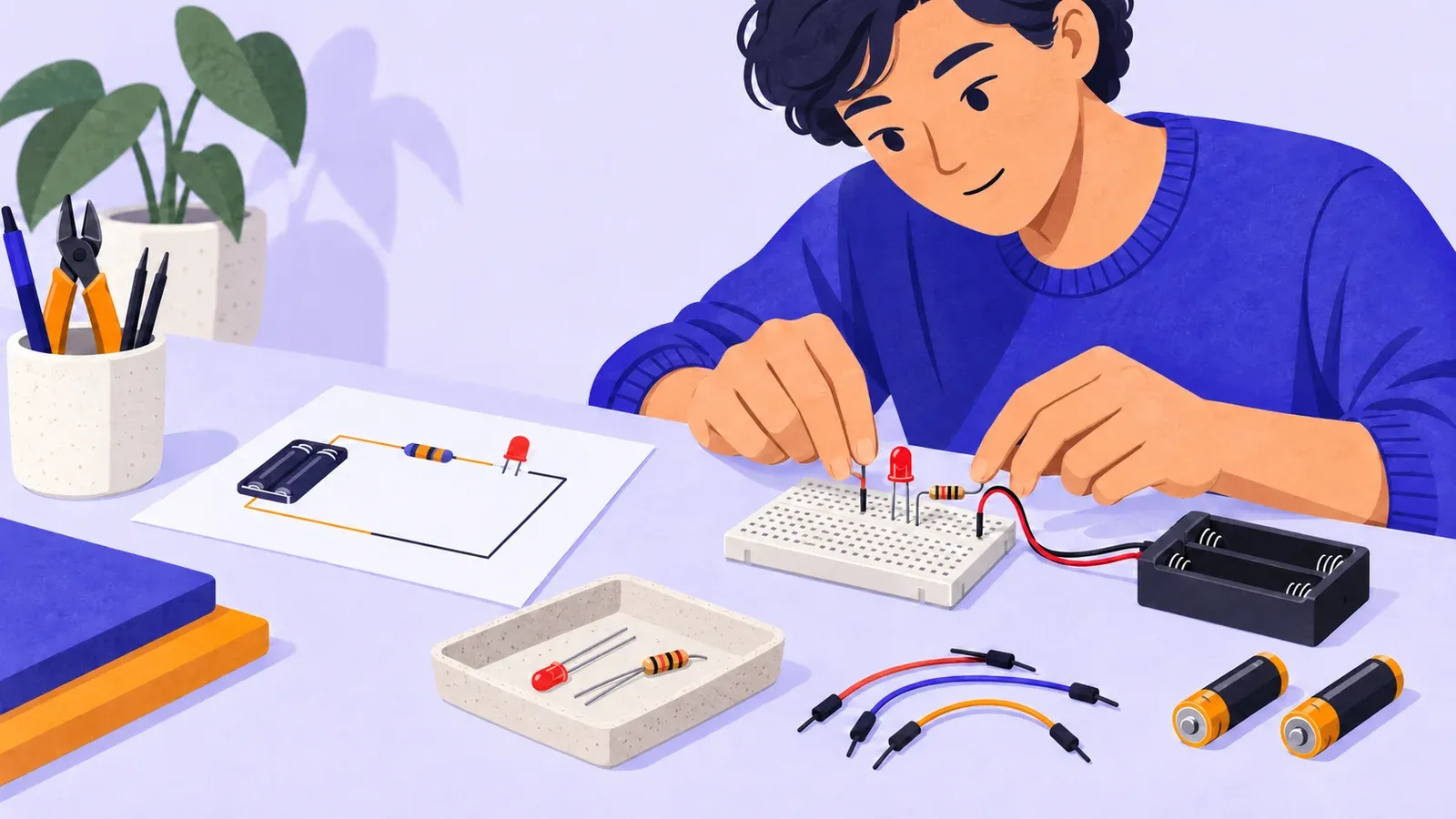
How to start electronics with one breadboard LED circuit
- Cost to start
- ~$10–30
- Difficulty
- Beginner
- First result
- 45–60 minutes
Breadboard, switched two-AA holder, cells, LED, resistor, and jumpers
Careful component placement; no soldering or programming
One safely powered LED that turns on and off at the holder
Build and troubleshoot a low-voltage LED circuit with two AA batteries, a resistor, and a solderless breadboard while learning safe power habits.
What you need to know
-
Stay with low-voltage battery power
Use a switched holder for two matching AA alkaline batteries. Do not connect this project to a wall outlet, household wiring, USB power, or a larger battery.
-
Include a current-limiting resistor
An LED must not be connected directly across the battery pack. Use the value specified by a matched tutorial or kit; this guide uses a 330-ohm resistor with a common red LED.
-
Build while the batteries are removed
Place and inspect every component before inserting cells. Switch off and remove at least one battery before changing the circuit or moving a wire.
-
Follow the hidden breadboard connections
Groups of holes are joined by metal strips underneath. Put leads in connected rows only when they should be the same electrical point.
-
Troubleshoot without guessing
Check power, LED direction, row placement, and component condition in order. Repeated random rewiring makes faults harder to identify and can create a short circuit.
Understand the loop before touching power
A circuit needs a source and a complete conductive path. Here, the two AA cells provide roughly three volts when fresh, the LED converts some electrical energy into light, and the resistor limits current.
Inspect, then apply power briefly
With the batteries removed, build the documented loop from holder positive through the 330-ohm resistor and LED to holder negative. Check the breadboard rows and LED direction. Insert matching cells with the switch off, clear loose metal, then switch on for two seconds. Stop for heat, smell, leakage, swelling, or smoke.
Troubleshoot one fact at a time
If the LED stays dark, switch off and remove one battery before touching the board. First confirm both cells face the holder markings. Second, check the LED direction. Third, compare every lead with the hidden row map. Fourth, confirm the resistor value.
Record the result and power down
Draw the final schematic and a simple breadboard map. Note battery type and count, resistor value, LED color and orientation, and the duration of the successful test. Photograph the board from directly above while power is off.

Understand and build the first circuit
- Adafruit breadboards for beginnersAn illustrated explanation of the conductive rows and rails, followed by a simple battery, LED, and resistor circuit without soldering.
- Adafruit guide to LEDsUse this specialist reference on LED polarity, voltage, current, resistors and brightness before designing another circuit.
- SparkFun Education on circuitsIntroduces closed paths, sources, loads, current, voltage, resistance, and short circuits using approachable diagrams and a physical LED example.

Battery care and technical questions
- Energizer battery careManufacturer guidance on polarity, mixing cells, storage, leakage, heat, and preventing metal objects from shorting battery terminals.
- r/AskElectronics posting guideThis moderated electronics guide explains the diagrams, photos, part details and measurements needed for a useful question.